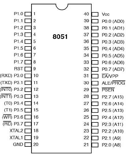
The pin diagram of 8051 microcontroller looks as follows −

- Pins 1 to 8 − These pins are known as Port 1. This port doesn’t serve any other functions. It is internally pulled up, bi-directional I/O port.
- Pin 9 − It is a RESET pin, which is used to reset the microcontroller to its initial values.
- Pins 10 to 17 − These pins are known as Port 3. This port serves some functions like interrupts, timer input, control signals, serial communication signals RxD and TxD, etc.
https://www.tutorialspoint.com/index.htm
No comments:
Post a Comment