Thursday, December 6, 2018

What is Microprocessor Input/Output Interfacing Overview

Interface is the path for communication between two components. Interfacing is of two types, memory interfacing and I/O interfacing.

Memory Interfacing

When we are executing any instruction, we need the microprocessor to access the memory for reading instruction codes and the data stored in the memory. For this, both the memory and the microprocessor requires some signals to read from and write to registers.
The interfacing process includes some key factors to match with the memory requirements and microprocessor signals. The interfacing circuit therefore should be designed in such a way that it matches the memory signal requirements with the signals of the microprocessor.

IO Interfacing

There are various communication devices like the keyboard, mouse, printer, etc. So, we need to interface the keyboard and other devices with the microprocessor by using latches and buffers. This type of interfacing is known as I/O interfacing.

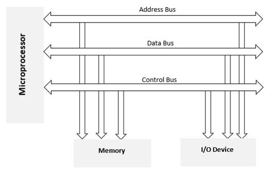
Block Diagram of Memory and I/O Interfacing

Interfacing

What is 8087 Numeric Data Processor

8087 numeric data processor is also known as Math co-processor, Numeric processor extension and Floating point unit. It was the first math coprocessor designed by Intel to pair with 8086/8088 resulting in easier and faster calculation.
Once the instructions are identified by the 8086/8088 processor, then it is allotted to the 8087 co-processor for further execution.
The data types supported by 8087 are −
  • Binary Integers
  • Packed decimal numbers
  • Real numbers
  • Temporary real format
https://www.tutorialspoint.com/index.htm

What is Multiprocessor Configuration?

Multiprocessor means a multiple set of processors that executes instructions simultaneously. There are three basic multiprocessor configurations.
  • Coprocessor configuration
  • Closely coupled configuration
  • Loosely coupled configuration

Coprocessor Configuration

A Coprocessor is a specially designed circuit on microprocessor chip which can perform the same task very quickly, which the microprocessor performs. It reduces the work load of the main processor. The coprocessor shares the same memory, IO system, bus, control logic and clock generator. The coprocessor handles specialized tasks like mathematical calculations, graphical display on screen, etc.
The 8086 and 8088 can perform most of the operations but their instruction set is not able to perform complex mathematical operations, so in these cases the microprocessor requires the math coprocessor like Intel 8087 math coprocessor, which can easily perform these operations very quickly.

Block Diagram of Coprocessor Configuration

Coprocessor Configuration

https://www.tutorialspoint.com/index.htm

What is Microprocessor 8086 Addressing Modes?

The different ways in which a source operand is denoted in an instruction is known as addressing modes. There are 8 different addressing modes in 8086 programming −

Immediate addressing mode

The addressing mode in which the data operand is a part of the instruction itself is known as immediate addressing mode.

Example

MOV CX, 4929 H, ADD AX, 2387 H,  MOV AL, FFH 

Register addressing mode

It means that the register is the source of an operand for an instruction.
https://www.tutorialspoint.com/index.htm

What is Microprocessor 8086 Interrupts?

Interrupt is the method of creating a temporary halt during program execution and allows peripheral devices to access the microprocessor. The microprocessor responds to that interrupt with an ISR (Interrupt Service Routine), which is a short program to instruct the microprocessor on how to handle the interrupt.
The following image shows the types of interrupts we have in a 8086 microprocessor
Interrupts

Hardware Interrupts

Hardware interrupt is caused by any peripheral device by sending a signal through a specified pin to the microprocessor.
The 8086 has two hardware interrupt pins, i.e. NMI and INTR. NMI is a non-maskable interrupt and INTR is a maskable interrupt having lower priority. One more interrupt pin associated is INTA called interrupt acknowledge.

NMI

It is a single non-maskable interrupt pin (NMI) having higher priority than the maskable interrupt request pin (INTR)and it is of type 2 interrupt.
  • Completes the current instruction that is in progress.
  • Pushes the Flag register values on to the stack.
  • Pushes the CS (code segment) value and IP (instruction pointer) value of the return address on to the stack.
  • IP is loaded from the contents of the word location 00008H.
  • CS is loaded from the contents of the next word location 0000AH.
  • Interrupt flag and trap flag are reset to 0.INTR
The INTR is a maskable interrupt because the microprocessor will be interrupted only if interrupts are enabled using set interrupt flag instruction. It should not be enabled using clear interrupt Flag instruction.
The INTR interrupt is activated by an I/O port. If the interrupt is enabled and NMI is disabled, then the microprocessor first completes the current execution and sends ‘0’ on INTA pin twice. The first ‘0’ means INTA informs the external device to get ready and during the second ‘0’ the microprocessor receives the 8 bit, say X, from the programmable interrupt controller.
https://www.tutorialspoint.com/index.htm

What is Microprocessor 8086 Instruction Sets

  • Data Transfer Instructions
  • Arithmetic Instructions
  • Bit Manipulation Instructions
  • String Instructions
  • Program Execution Transfer Instructions (Branch & Loop Instructions)
  • Processor Control Instructions
  • Iteration Control Instructions
  • Interrupt Instructions
Let us now discuss these instruction sets in detail.

Data Transfer Instructions

These instructions are used to transfer the data from the source operand to the destination operand. Following are the list of instructions under this group −

Instruction to transfer a word

  • MOV − Used to copy the byte or word from the provided source to the provided destination.
  • PPUSH − Used to put a word at the top of the stack.
  • POP − Used to get a word from the top of the stack to the provided location.
  • PUSHA − Used to put all the registers into the stack.
  • POPA − Used to get words from the stack to all registers.
  • XCHG − Used to exchange the data from two locations.
  • XLAT − Used to translate a byte in AL using a table in the memory.

Instructions for input and output port transfer

  • IN − Used to read a byte or word from the provided port to the accumulator.
  • OUT − Used to send out a byte or word from the accumulator to the provided port.

Instructions to transfer the address

  • LEA − Used to load the address of operand into the provided register.
  • LDS − Used to load DS register and other provided register from the memory
  • LES − Used to load ES register and other provided register from the memory.

Instructions to transfer flag registers

  • LAHF − Used to load AH with the low byte of the flag register.
  • SAHF − Used to store AH register to low byte of the flag register.
  • PUSHF − Used to copy the flag register at the top of the stack.
  • POPF − Used to copy a word at the top of the stack to the flag register.
https://www.tutorialspoint.com/index.htm

What is Microprocessor 8086 Pin Configuration?

8086 was the first 16-bit microprocessor available in 40-pin DIP (Dual Inline Package) chip. Let us now discuss in detail the pin configuration of a 8086 Microprocessor.

8086 Pin Diagram

Here is the pin diagram of 8086 microprocessor −
8086 Pin Diagram
https://www.tutorialspoint.com/index.htm